FATRAT (v2) uses 2 PCB's to contain the small CPU modules and other support circuitry for data acquisition.
Power is supplied by a 7.4V Li-ION battery pack.
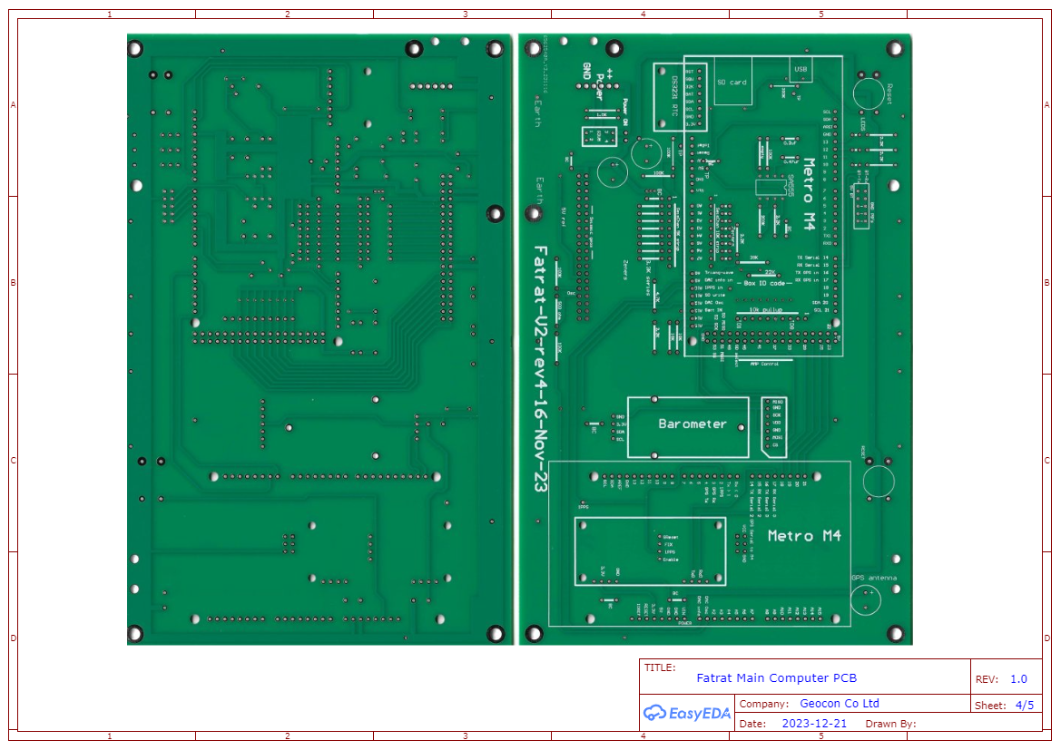
MAIN CPU Board
This board houses 2 x Metro M4 CPU boards from Adafruit called the "Grand Central". The CPU on these boards runs at 120Mhz and has 16 ADC inputs and 2 DAC inputs plus 72 GPIO pins.
A Real Time Clock from Adafruit DS3231, is also mounted on the board along with an Adafruit GPS Featherwing GPS board and a Seeed Studio HP206C Barometer with temperature sensor.
A small circuit using a common SA555 chip creates a "pseudo" triangular wave running at a frequency around 7Hz is input directly to an ADC channel as a reference signal to check for any data glitches in writing buffers to the SD card storage.
The board has some external connectors
- 10 pin connector for Bluetooth module and external button control of the board mode of operation; STANDBY, GPS MONITOR and DATA ACQUIRE.
- 7 pin connector for an external SD card
- 20 pin connector to connect to the second AMPLIFIER board
The board has 3 LED's used to indicate which mode the board is currently operating in.
The board also contains some jumpers that can be drilled out to form an 8 pin digital byte to identify the board i.e. serial number. Values can be from 0 to 255. This is referred to as the "Box ID code".
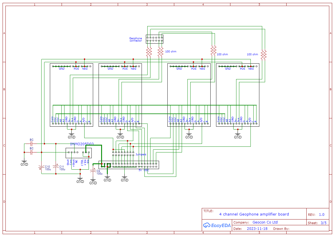
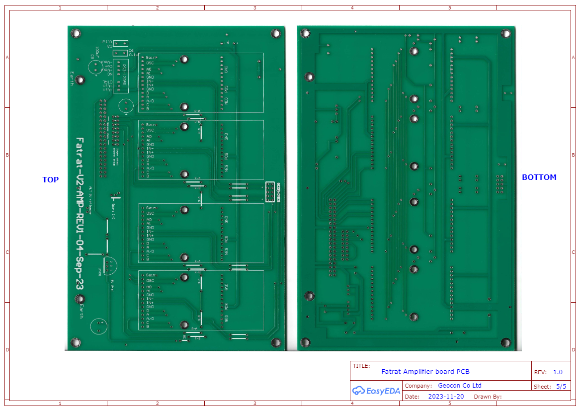
AMPLIFIER BOARD
This second board contains 4 x Fatrat v7 amplifer daughter boards and a power supply module that produces +/- 3.3V to power the amplifiers.
A 2 x 8 pin jumper block is used to select which channels the 4 amplifiers are connected to on the MAIN CPU board.
Two AMPLIFIER BOARDS are needed and simply piggy backed by the 20 pin connector, each board with differing jumper settings. Board 1 would have jumpers 1-4 selected so output is directed to channels 0 - 3 of the ADC on MAIN CPU board. Board 2 would have jumpers 5-8 selected so output is directed t0 channels 4 - 7 of ADC.
An 12 pin (2 x 6 row) connector is used to connect geophones to each board.
The circuits for these 2 main boards are shown below